Install and Use the EPIC Lockdown Button
Quick Reference QR-AE-023 · Audio Enhancement EPIC · Rev 1.4 · Oct 2026
Plan, mount and wire the blue EP-2011 Lockdown Button to an EPIC device input (RJ45 or Phoenix), and set up EPIC so one press starts the Lockdown event.
📄 View or download this guide as a PDF
Click the PDF icon below to open it right here in your browser. In the viewer, use Download (top right) to save a copy, or the printer icon to print it.
The EPIC Lockdown Button is a hard-wired push button that starts EPIC's Lockdown notification. Use it where a kiosk won't fit or where staff want a physical button (main office, nurse, a secured entry). It has a lift cover so it can't be bumped by accident, and a white light so people can find it in the dark. It's just a contact closure into an EPIC device input: EPIC does the rest.
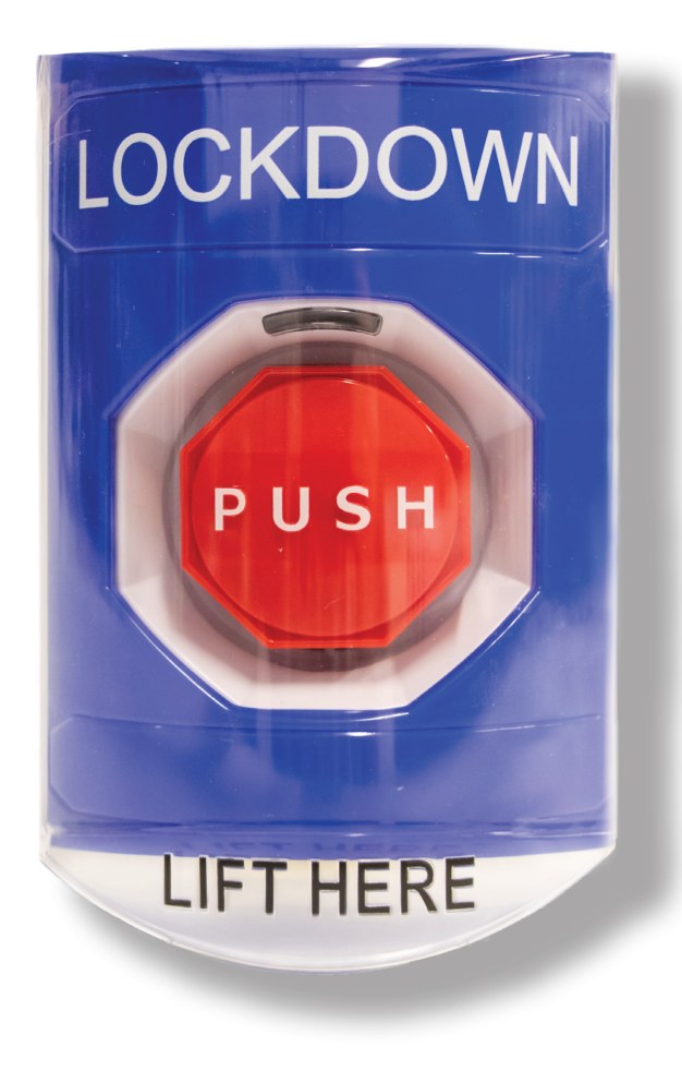
EPIC Lockdown Button: lift the cover, press PUSH. Audio Enhancement.
| Spec | EP-2011 |
|---|---|
| Contacts | Two Form C, rated 10 A @ 125/250 VAC |
| Light | White LED, 12 to 24 VAC/VDC |
| In the box | Button with cover, back box, extension ring (the manual also lists a CAT6 patch cable and an RJ45 breakout adapter) |
| Size | 4.86 H × 3.22 W × 3.62 D in |
| Listings | UL/cUL, ADA compliant · over 100,000 presses |
| Distance | Up to 300 ft to the device (CAT5e/CAT6, or 18 to 22 AWG such as 22/4) |
1️⃣ Plan it before the install
| Decide | Notes |
|---|---|
| Where it goes | Wherever the district's safety plan wants a physical button: main office, nurse, secured entry, principal's office. Keep the button inside ADA reach range (15 to 48 in. above the floor) and where a visitor can't reach it first. |
| What it starts | Normally the Lockdown event. The district decides what that event does (message, strobes, doors, texts and emails). The button just starts it. |
| Which device and input | The nearest EPIC device with a free input, within 300 ft of cable (step 2). It can be a classroom device that's already in a zone. |
| Light or no light | The white light needs +24 V from the device. RJ45 ports have it; the Phoenix GPI blocks on the MS-720, MS-775 and CZA-1300 don't (step 2). |
| A second system? | The button has two separate Form C contacts. Use one for EPIC and, if the district wants, the other for another system (for example an access control lockdown input). Never share one contact between two systems. |
| More than one button | Each button gets its own input. All of them are added as triggers on the same event (step 6). |
2️⃣ Pick the device and input
Two kinds of connection, depending on the device:
| Device | Connector | Input to use | Light |
|---|---|---|---|
| MS-700, MS-700-S | RJ45 | GPIO 3&4 port: Input 3 on pin 3 (Input 4 on pin 6 is a second spare) | Yes: +24 V on pin 4, GND on pin 5, same port. |
| MS-500, MS-600 (older) | RJ45 | I/O port: In #1 on pin 3. These devices only have In #1 (Call) and In #2 (Emergency), so the button needs a device with no wall plate, or a room that gives up its Call button. | Yes: +24 V on pin 4, GND on pin 5. |
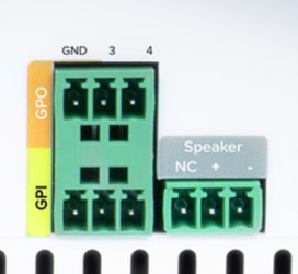
| MS-720, MS-775, CZA-1300 | 3-pin Phoenix (GPI) | GPI 3 (pin 2) and GND (pin 1). GPI 4 (pin 3) is a second spare. Inputs 1 and 2 are on the WPA port and belong to the wall plate (Call, Emergency). | No. The GPI block has no +24 V, so the button works but stays dark. Don't take power from another port for it. |
RJ45 I/O port pinout (T568-B). On the MS-700 GPIO 3&4 port, pin 3 is Input 3, pin 6 is Input 4, pin 4 is +24 V and pin 5 is GND. Audio Enhancement.
MS-720 / MS-775 GPO (top) and GPI (bottom) Phoenix blocks: pin 1 GND, pin 2 = 3, pin 3 = 4. The CZA-1300 GPI is the same. Audio Enhancement.
3️⃣ Mount the button
- Use the back box and the extension ring together. They give you room for the terminations.
- On a roughed-in electrical box, the extension ring is required.
- Surface mount: four #6 × 1-1/4 in. screws and anchors (provided). The back box has drill points top and bottom for 1/2 in. conduit fittings.
- Fit the button-and-switch assembly with the two #6-32 screws, then slide the housing on and lock it at the bottom with the Allen screw (3/32 in. hex wrench included).
- Run cable from the button to the device: CAT5e/CAT6, or plain low-voltage wire such as 22/4 or 18/4 (18 to 22 AWG). You need 2 conductors for the contact, 4 if the light is used. AE rates the button up to 300 ft from the device. Keep the run in conduit or above the ceiling where it can't be pulled.
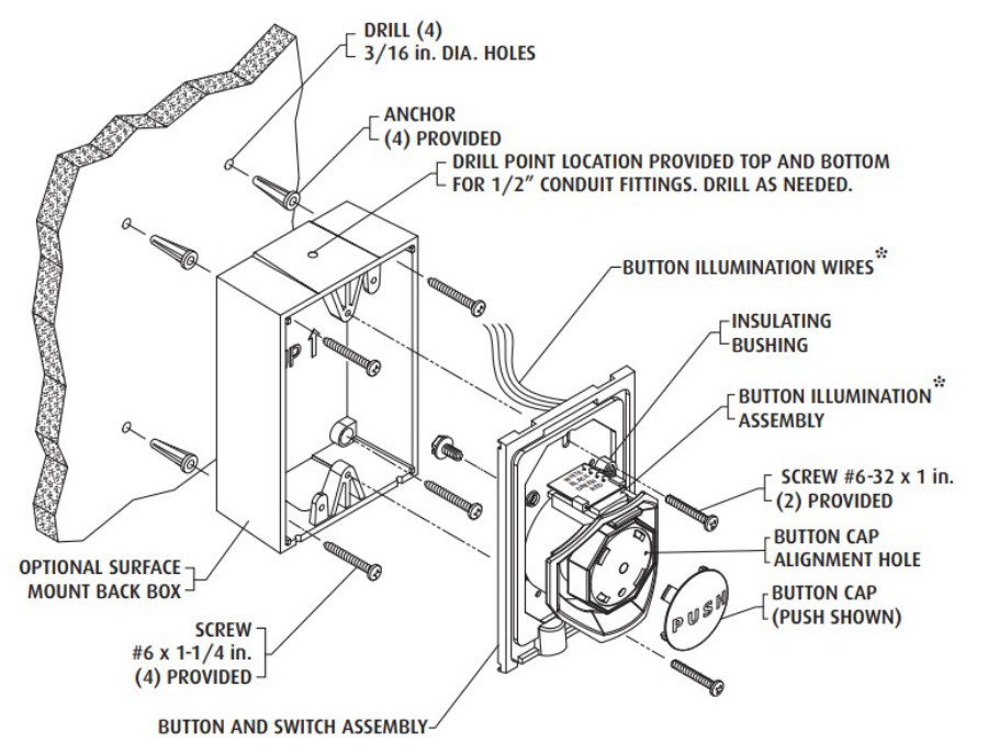
Back box, button assembly and illumination wires. Audio Enhancement, DC-40970.01.
4️⃣ Wire it to an RJ45 port (MS-700, MS-700-S, MS-500, MS-600)
Two connections: the trigger contact and the light. Both land on the screw terminals of the RJ45 breakout adapter in the kit, which plugs into the device with the CAT6 patch cable. That works with CAT cable or with 18 to 22 AWG wire such as 22/4. With CAT cable you can instead terminate an RJ45 (T568-B) and plug straight into the port.
| From the button | RJ45 pin | CAT (T568-B) color |
|---|---|---|
| Contact NO | Pin 3 (the input) | White/green |
| Contact COM | Pin 5 (GND) | White/blue |
| Light white wire | Pin 4 (+24 V) | Blue |
| Light black wire | Pin 5 (GND, shared with COM) | White/blue |
To use the second spare input on an MS-700 GPIO 3&4 port, land NO on pin 6 (green) for Input 4 instead of pin 3.
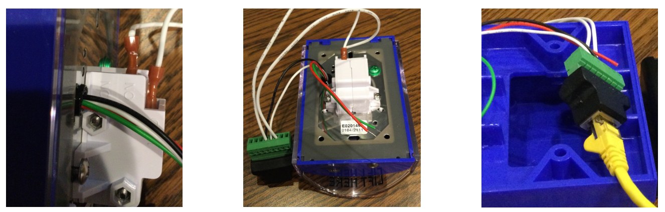
Light wires on the button (left), contact and light leads to the breakout adapter (center), patch cable into the adapter (right). Audio Enhancement, DC-40970.01.
5️⃣ Wire it to a Phoenix GPI (MS-720, MS-775, CZA-1300)
| From the button | GPI Phoenix plug | Suggested conductor (CAT / 22/4) |
|---|---|---|
| Contact NO | Pin 2 (GPI 3) | White/green · or green |
| Contact COM | Pin 1 (GND) | White/blue · or black |
| Light wires | Not connected | Cap and tuck them in the back box. |
- No breakout adapter: strip the cable (CAT or 22/4) at the device and land the two conductors in the GPI plug. Tighten and tug-test each one. On stranded wire, twist the strands tight (or use a ferrule) so no strand shorts to the next pin.
- For a second button on the same device, land its NO on pin 3 (GPI 4) and its COM on the same GND pin.
- Use the GPI block (inputs), not the GPO block next to it (outputs).
6️⃣ Set up the device and trigger in EPIC
- If the device is new, add and configure it in EPIC like any other device.
- If the device is dedicated to the button, name it with LOCKDOWN in it (for example
MES-LOCKDOWN) and give it an extension at the end of, or outside, the room ranges (for example3999). - MS-500 / MS-600 on In #1 only: pencil icon on the device › Advanced › clear Call Button Extension to Dial so a press doesn't also place an office call. Save.
- Settings › Events, open the Lockdown event.
- On the left, under When any of these happen, pick Devices - A device detects a change, then + Add Device.
- Select Device Type (for example MS-700 or MS-720), pick the device, then the input in the Closed state: Input 3 Closed on an MS-700, MS-720, MS-775 or CZA-1300; Input 1 Closed on an MS-500 or MS-600. The button is normally open, so a press closes it.
- Click Add Device. For more buttons, repeat for each device and input. Save the event.
7️⃣ Test it with the district
- Schedule it with the office and the district: a press is a real, building-wide Lockdown. If the event sends texts, emails or calls outside the building, warn those people too.
- RJ45 devices: check the button is lit white.
- Lift the cover, press PUSH and let go. On an MS-720, MS-775 or CZA-1300, the GPIO Status light turns yellow while the input is closed.
- The Lockdown event starts and its message plays through the building. Check each action the district expects (doors, strobes, notifications).
- End it the way the district does (usually All Clear from the kiosk or console). If the message loops, stop it there.
- Record the device, input, location and test date in the project.
8️⃣ Using the button
- On RJ45 devices the button is lit white when it's powered and ready. On Phoenix GPI devices it's never lit.
- To start a lockdown: lift the cover, press PUSH, then let go.
- Everything tied to the Lockdown event runs. Only the kiosk or console ends it, following the district's procedure.
Field tips
- Light off (RJ45 device)? Check pin 4 (+24 V) and pin 5 (GND) at the breakout and that the device has PoE.
- Nothing happens on a press? Meter NO to COM: it should close on a press. On a Phoenix device, check the GPIO Status light goes yellow. Then check the event's device, input number and Closed state.
- Lockdown starts by itself? The wiring is on NC instead of NO, or the trigger is set to Open instead of Closed.
- Office call rings instead? The button is on a Call input with the call extension still set (step 6).
- Doors toggle missing or a blank box on the home screen? Someone changed the Lockdown Event Name. Set it back to
lockDown. - EPIC can't tell if the cable is cut. Include the button in the district's lockdown drills so it gets tested.
📚 Sources & credits
- Compiled by Brad Roy, VSC Director of Operations
- Audio Enhancement: EPIC Lockdown Button Manual DC-40970.01 (hardware, mounting, cabling, device setup, testing); EPIC Lockdown Button Spec Sheet DC-40971.02 (specifications, two Form C contacts); MS-700 Optimum System Pinout DC-41213.0925 (GPIO 3&4 port); MS-700-S QSG DC-41151.1025; MS-600 Pinout DC-41019.0825 (I/O port, only two inputs); MS-720 and MS-775 Pinouts DC-41214.1025, DC-41215.1025 and Spec Sheets / QSGs DC-41099.1025, DC-41100.1025, DC-41098.1025, DC-41101.1025 (GPI Phoenix, inputs 3 and 4, GPIO Status light); CZA-1300 Manual DC-41133.0525 (GPI Phoenix pins)
- Phoenix connections, the unlit button on GPI devices, and 18 to 22 AWG (22/4) cabling: Brad Roy, VSC (10/12/2026). ADA reach range: 2010 ADA Standards, section 308.
- AE's Lockdown Button manual and spec sheet are older, undated AE documents (written for EPIC System V2). The EPIC 3.x trigger steps follow EPIC 3.x's device-change trigger. Images: Audio Enhancement.