Wiring the MS-700 Optimum System
Quick Reference QR-AE-031 · Audio Enhancement EPIC · Rev 1.1 · Oct 2026
Every port on the MS-700 classroom amp: what plugs where, the RJ45 pinouts, speakers and PA mute, the wall plate, and the integrated wall box.
📄 View or download this guide as a PDF
Click the PDF icon below to open it right here in your browser. In the viewer, use Download (top right) to save a copy, or the printer icon to print it.
The MS-700 is the classroom amp in most of our EPIC rooms. It has a built-in XD receiver for the teacher and student mics, and the whole unit runs on PoE+: one network cable powers it, connects it to EPIC and feeds 24 V to the wall controls. Get the ports right and the room works the first time it powers up.
1️⃣ Learn the connector panel
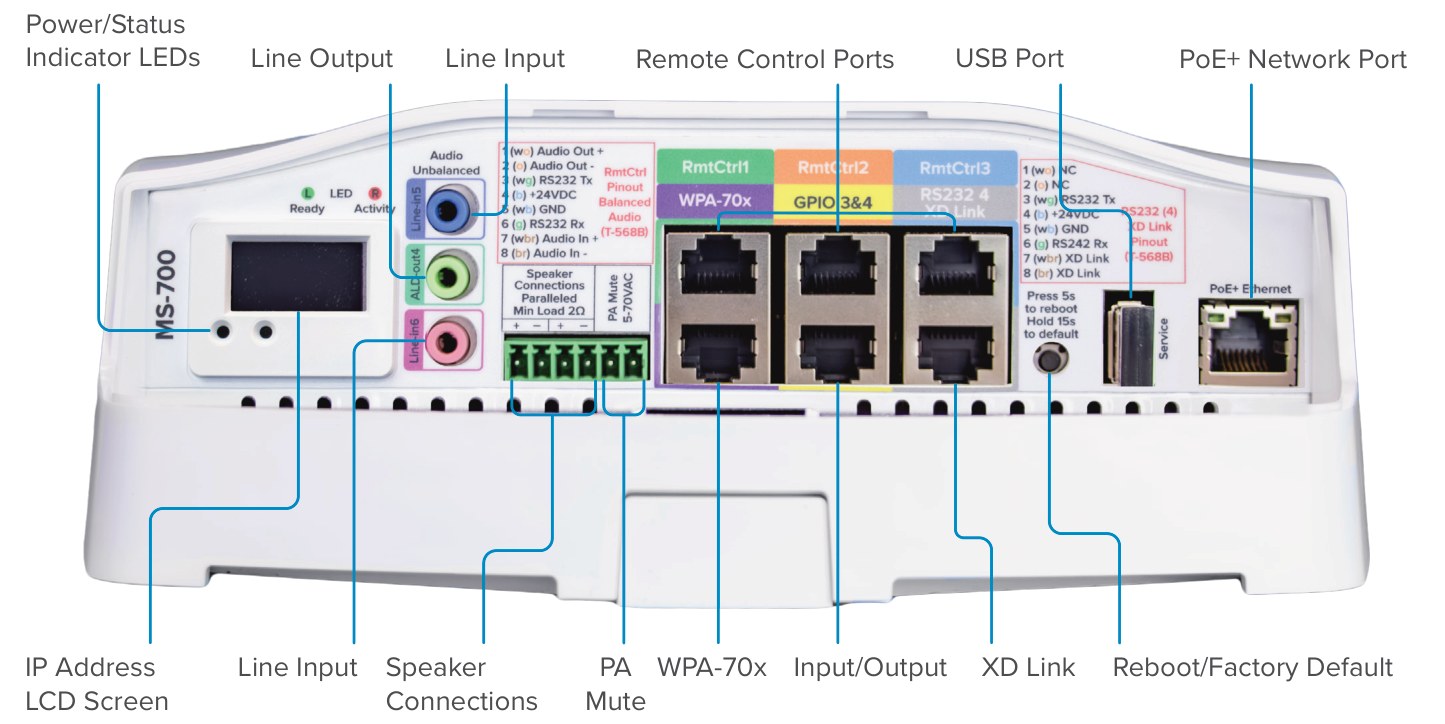
MS-700 connector panel. Six RJ45s in two rows of three, color-coded: RmtCtrl 1/2/3 on top; WPA-70x, GPIO 3&4 and RS232 4 / XD Link underneath. The pinouts are printed on the panel too.
| Port (panel label) | Connector | What plugs in |
|---|---|---|
| PoE+ Ethernet | RJ45, far right | The network. Must be 802.3at (PoE+). Powers the whole unit. |
| RmtCtrl 1, 2, 3 | RJ45, top row | AE wall controls such as the ITC2 (LCD wall plate). Each has balanced audio in and out, RS-232 and 24 V. |
| WPA-70x | RJ45, under RmtCtrl 1 | AE wall plate: Call and Emergency buttons and a room mic. |
| GPIO 3&4 | RJ45, under RmtCtrl 2 | Two inputs and two outputs (sensors, strobes and similar). The QSG callout calls it Input/Output. |
| RS232 4 / XD Link | RJ45, under RmtCtrl 3 | Serial port 4 plus the XD pairing lines and 24 V. |
| Line-in5 (blue), Line-in6 (pink) | 3.5 mm | Unbalanced audio in from a PC, media player or aux mic. |
| ALD-out4 (green) | 3.5 mm | Unbalanced line output. Also your headphone test point. |
| Speaker Connections + PA Mute | 6-pin green Phoenix | Two paralleled speaker pairs, then the two PA Mute pins (step 3). |
| Service USB | USB-A | Service only: the BLE USB adapter goes here, so AE's Device Configuration phone app can connect over Bluetooth. |
| Reset button | Pinhole | Press 5 s to reboot. Factory default: see Field tips. |
The LCD shows the IP address, firmware version and a PoE+ warning. The Ready and Activity LEDs sit next to it.
2️⃣ Terminate the RJ45 ports (T568B)
All six jacks are wired T568B. The same 8-pin layout repeats: pin 4 is +24 V DC and pin 5 is GND on every one. Only the PoE+ jack is Ethernet.
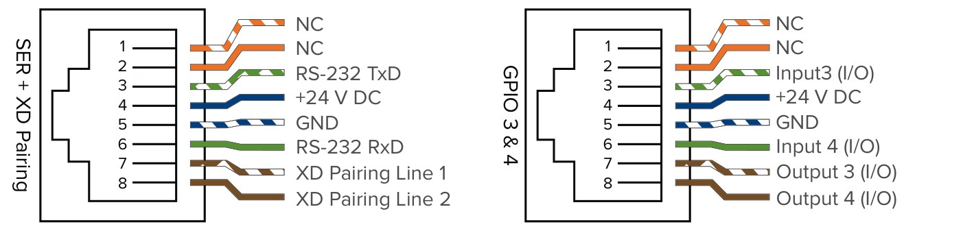
Remote Control (RmtCtrl 1–3) and WPA.
SER + XD Pairing and GPIO 3 & 4.
| Pin | T568B color | RmtCtrl 1, 2, 3 | WPA-70x | RS232 4 / XD Link | GPIO 3&4 |
|---|---|---|---|---|---|
| 1 | White/orange | + Line Level Out | + Mic | NC | NC |
| 2 | Orange | − Line Level Out | − Mic | NC | NC |
| 3 | White/green | RS-232 TXD | I/O In #1 (Call) | RS-232 TxD | Input 3 |
| 4 | Blue | +24 V DC | +24 V DC | +24 V DC | +24 V DC |
| 5 | White/blue | GND | GND | GND | GND |
| 6 | Green | RS-232 RXD | I/O In #2 (Emergency) | RS-232 RxD | Input 4 |
| 7 | White/brown | + Line Level In | I/O Out #1 | XD Pairing Line 1 | Output 3 |
| 8 | Brown | − Line Level In | I/O Out #2 | XD Pairing Line 2 | Output 4 |
Transcribed from AE DC-41213.0925 and the QSG connector details. NC = no connection.
3️⃣ Land the speakers and PA mute
- The green 6-pin Phoenix reads, left to right: Spkr + − + −, then PA Mute (2 pins).
- The two speaker pairs are paralleled inside the amp, so both pairs carry the same output.
- Load: 4 Ω minimum on each pair, 2 Ω minimum overall. Output is 30 W from PoE (depends on the switch).
- PA Mute: connects to the building's public address system. When 5–70 VAC is present on these pins the MS-700 mutes, so the PA announcement is heard.
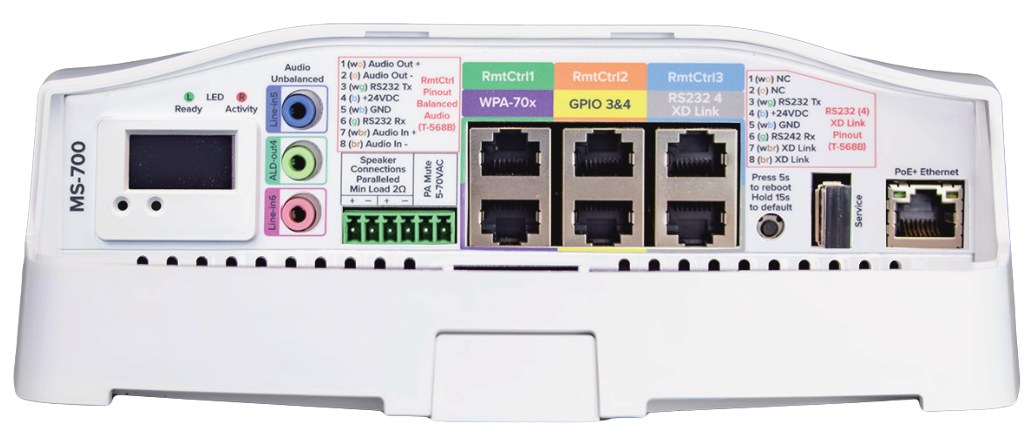
Panel close-up: 3.5 mm jacks, the speaker/PA Mute Phoenix and the RJ45 rows with their color labels.
4️⃣ Connect the network last
- Use a switch port that supplies IEEE 802.3at (PoE+). The LCD can show a PoE+ warning.
- Every wall control you add draws its 24 V from the MS-700's PoE budget. AE notes a constantly rebooting MS-700 with peripherals like an ITC attached may be pulling too much power.
- After power-up: rear Power and Status LEDs are red while booting, then green. Status blinks green with network activity.
5️⃣ Mount the integrated wall box
The MS-700 lives in AE's Integrated Enclosure. The kit has the wall-mount bracket, the enclosure, (4) #12 × 1-1/2" Phillips screws, (4) #12 × 1" plastic drywall anchors and (2) 10-32 × 3/8" machine screws.
- Wall: level and center the bracket, mark and drill four 1/4" holes, insert the anchors. Drill out the center routing hole if you need it. Screw the bracket on.
- Ceiling tile: take the tile down, center the bracket, drill four 1/4" holes plus a center hole for cables, insert anchors. Put the tile bridge on the back of the tile and screw through it.
- Route cables through the bracket's center hole (from behind the surface) or the wire molds at the top or bottom.
- Set the enclosure on the bracket and slide it down. Feed the cables in through the back opening and secure it with the two 10-32 screws.
- Make your connections, test the system, then reinstall the front access panel on the bottom.
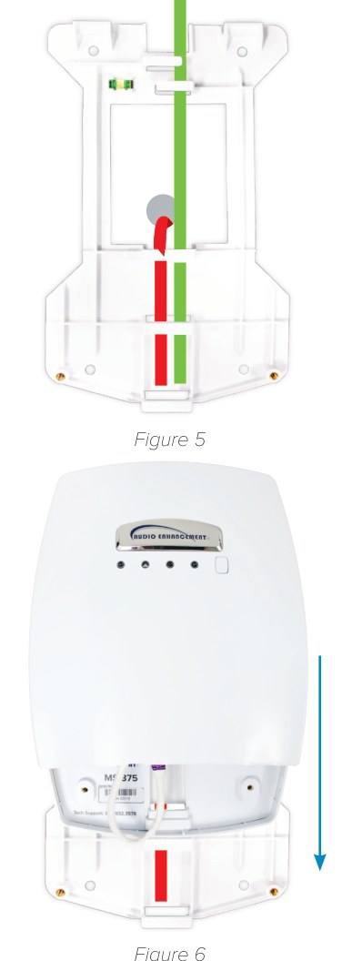
Bracket cable paths (red: center hole; green: wire molds) and sliding the enclosure down onto the bracket.
6️⃣ Read the front LEDs
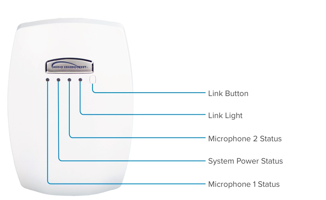
Front of the enclosure: Mic 1, System Power, Mic 2, Link light, Link button.
| LED | Meaning |
|---|---|
| Microphone 1 | Green: mic 1 connected |
| System Power | Green: powered on |
| Microphone 2 | Green: mic 2 connected |
| Link light | Blinking yellow: linking. Solid yellow: media channel linked |
| Link button | Starts mic linking: press it (Link light blinks yellow), then put the mic in link mode. Teacher pendant: mic off, hold REC, then hold PWR until it links. A beep and an extra green LED confirm it. |
Pre-power checklist
| ✓ | Before the PoE+ cable goes in |
|---|---|
| ☐ | Every RJ45 terminated T568B and tested; each cable is in the jack its label says (RmtCtrl, WPA-70x, GPIO, XD Link). |
| ☐ | No AE port is patched to a switch or data jack; the only network cable is in PoE+ Ethernet. |
| ☐ | Speakers landed + to + and − to − on the speaker pins; nothing below 4 Ω on either pair. |
| ☐ | PA Mute (if used) landed on the two PA Mute pins, not on a speaker pair. |
| ☐ | The switch port is 802.3at PoE+, and the number of wall controls on this amp is what the drawings show. |
| ☐ | Enclosure seated on its bracket with both 10-32 screws in; cables strain-free through the back opening. |
| ☐ | Front access panel left off until the room has been tested. |
Field tips
- No sound from the speakers? Plug wired headphones into ALD-out4 and play audio. If you hear it, the amp is fine; check the speakers and speaker wiring.
- Reboot vs factory default: press the reset button 5 s to reboot. AE's QSG says hold 10 s until the Status LED flashes green to factory-reset; the panel print says "Hold 15s to default". Hold until the LED flashes.
- Replacing a dead MS-700? Move every cable to the same port, then follow QR-AE-012.
- Next steps: link the mics (QR-AE-013) and set room volumes (QR-AE-011).
📚 Sources & credits
- Compiled by Brad Roy, VSC Director of Operations
- Audio Enhancement: MS-700 Optimum System Pinout Guide DC-41213.0925 (RmtCtrl, WPA, SER + XD Pairing and GPIO 3 & 4 pinouts; panel photo); MS-700 Optimum Amplifier Quick Start Guide DC-41034.0824 (panel callouts, interfaces, LEDs, PA mute, PoE+, troubleshooting)
- Audio Enhancement: MS-700 Optimum Amplifier Spec Sheet DC-40133.0124 (load impedance, power, PA connector range)
- Audio Enhancement: Integrated Enclosure Installation Guide DC-40944.0923 (an older AE document, Sep 2023; mounting, ceiling tile, cable routing)
- Images: Audio Enhancement.